Fiber-optic detectors BOS-VO
In a nutshell. The fiber-optic cable mounted on the fence or buried in the ground becomes the sensing element itself: any action — climbing over, cutting, footsteps nearby — changes the light signal inside the fibre, and the processing unit inside the guarded building registers the event. There is no electronics on the perimeter at all: the cable is passive, needs no power and is immune to electromagnetic interference. This is the most scalable type of vibration security — up to 25 km on a single cable.
BOS-VO is the flagship system for large sites with a long perimeter. A single fiber-optic cable becomes a continuous sensing element tens of kilometres long: it is invisible to the intruder, requires no power on the perimeter and is immune to electromagnetic interference. All the electronics sit in the guarded checkpoint — there is not a single device on the perimeter that needs protecting.
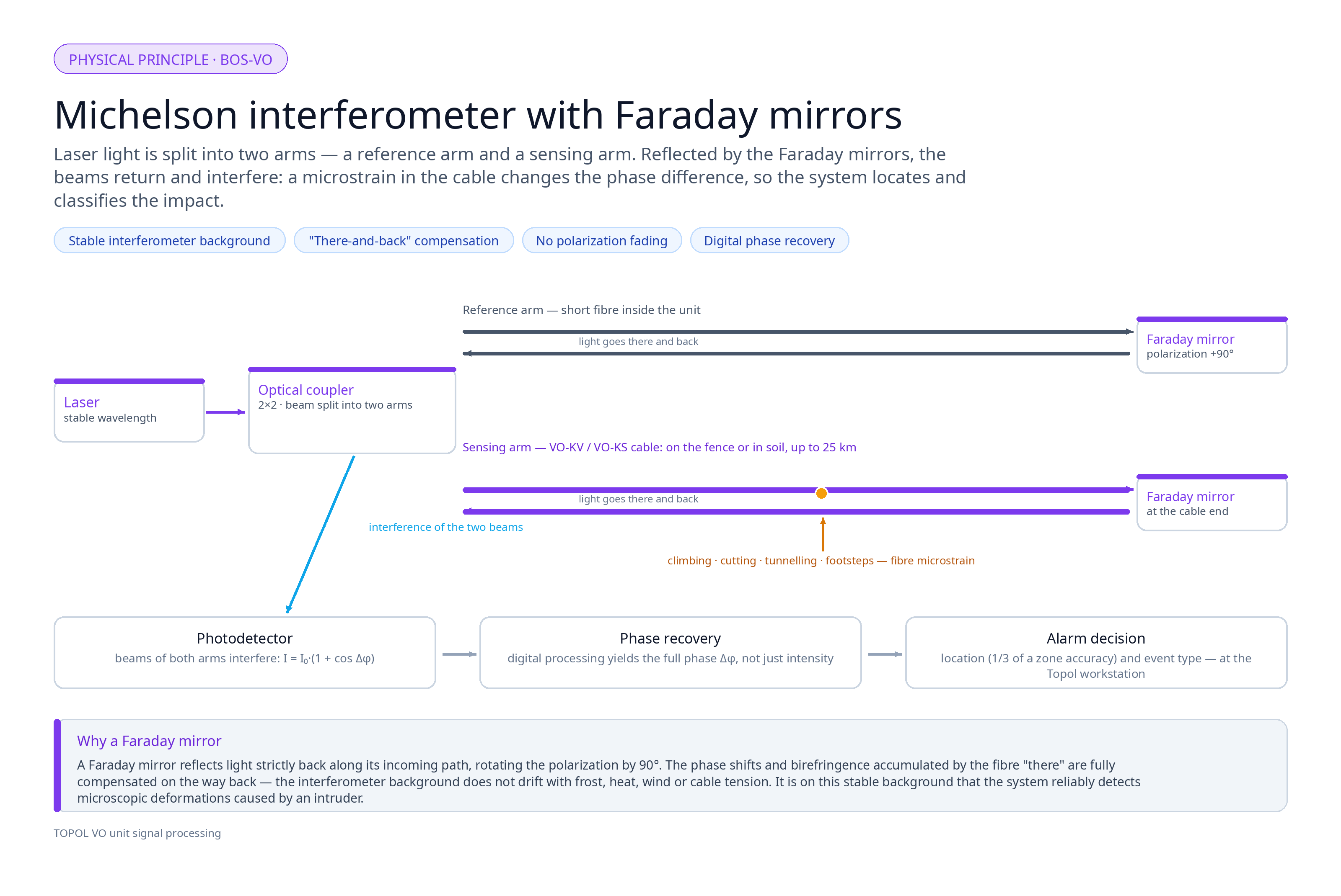
At the heart of the detector is a Michelson interferometer. When someone tries to climb or cut the fence, walk over a buried cable, or dig a tunnel, micro-deformations arise in the fibre that change the phase of the light signal. The interferometer registers the smallest phase shifts of the laser radiation — which provides ultra-high sensitivity and precise location of the action.

Third-generation interferometers
BOS-VO processing units are third-generation devices. At their core are fiber-optic interferometers with a phase recovery scheme: digital processing restores the full phase of the light signal, not just its intensity. This widens the measurement dynamic range — the system keeps its accuracy both for microscopic fibre deformations and for strong actions on it.
Reference sensitivity is provided by the use of Faraday mirrors. A Faraday mirror is an optical element that reflects light strictly back along the incoming path and rotates the polarisation plane by 90°. Unlike an ordinary rotator, its action is independent of the direction of light propagation: the phase shifts accumulated by the fibre "there and back" are compensated. That is why the interferometer background is stable under temperature changes and mechanical loads on the cable — and against a stable background the system reliably extracts even microscopic deformations caused by an intruder.
Intelligent signal processing
BOS-VO processing units make the alarm decision not by fixed thresholds but on the basis of artificial intelligence and big-data analysis:
- Continuous data stream. Each zone sends the processing unit a spectral "portrait" of the actions around the clock — large volumes of vibration and seismic data are accumulated over the whole perimeter.
- Machine learning. The algorithms learn the "fingerprints" of typical events: a person climbing, vehicle movement, animal footsteps, wind gusts, rain and hail. The system distinguishes a real threat from natural noise and classifies the alarm by threat level.
- Adaptability. The model adjusts to the specific site — time of day, season, weather, fence type, local interference sources. The longer the system works, the more accurate it gets: false alarms drop, sensitivity to real threats grows.
- Reasoned decision. The alarm is formed from the totality of event features — its spectrum, duration, spatial distribution and dynamics — rather than a single threshold crossing.
Why BOS-VO is the choice for large sites
For perimeters of kilometres and tens of kilometres, the fiber-optic architecture wins on every count:
- Scale. The sensitive part of the cable can be 25 km from the processing unit. One unit covers a perimeter for which conventional systems would need dozens of devices and hundreds of kilometres of communication lines.
- Centralisation. All electronics are in the guarded checkpoint or server room. There is not a single cabinet to protect on the perimeter: the cable is passive, needs no power (the processing unit is fed from ~220 V mains) and creates no radio interference for other equipment.
- Economics. A single backbone instead of many lines, one power source instead of dozens, a minimum of site cabinets — this substantially reduces installation and subsequent maintenance costs.
- Reliability. A zoned topology: if the backbone is damaged, the detector loses contact only with the zone where the break occurred, the rest keep working. The damaged section is repaired on site just like ordinary telecommunications cable — by standard fibre splicing, with no special tools or spare parts.
- Interference immunity. Optical cable does not react to radio waves — it can be laid next to generators, radars, radio beacons, power lines and other radio-emission sources.
- Durability. The cable service life is over 25 years, the operating temperature range is from −60 °C to +70 °C.

A single system with all sensor types
BOS-VO can become the core of a multi-layer system: all types of sensing elements based on different physical principles are joined into one Topol network. The configuration is selected for each perimeter section — by fence type, terrain and security-line requirements:
| Perimeter section | Sensing element | Physical principle |
|---|---|---|
| Long stretches (up to 25 km) | BOS-VO optical cable | Light interferometry |
| Critically important and heavily noisy sections | Addressable vibration sensors VD-3, VD-5, VD-5-K | MEMS accelerometry |
| Approach to the perimeter, sections without a fence | Seismic sensors SD-3 | Piezoelectric effect |
| Economical sections, coping arms, razor wire | Triboelectric cable TD-1 (DD-1) | Triboelectric effect |
Addressable and linear sensors connect to the backbone through BOS-L linear units — over RS-485 or directly over the fiber-optic line: the backbone cable simultaneously carries the sensing element and the communication channels for the TOPOL and BOS processing units. So all security lines work on one site — vibration, seismic, anti-tunnel — with a single processing centre and a single operator interface.
The BOS-VO processing unit has its own built-in data collection and processing system, which allows it to be used as the central server of the entire security system: a single centre for receiving data from all security lines, storing events and managing the system.
The detector is delivered fully assembled at the factory: to start it up, it is enough to mount the cable on the fence and connect the processing unit to ~220 V, 50 Hz AC mains. No power is required on the perimeter. The processing unit performs automatic self-commissioning on site: after connection it determines the sensitive zone parameters itself and is brought into the operating state — with no manual tuning and no visiting engineer.
The sensing element is ordinary telecommunications optical cable — standard and affordable, it does not have to be specially ordered. The cable can also be manufactured directly on site from standard communications fibre-optic cable and a splice-closure kit made by NPFP Poliservis.
The sensing element can be a single cable for the whole perimeter or split into several parts to organise opposing lines. Zoning depends on the processing unit model: 8, 11, 22, 24 or 33 zones (TOPOL VO/19-B-8, -11, -22, -24, -33) from 1 to 300 m each, or 48 zones (TOPOL VO/19-B-48) from 50 to 200 m. For difficult operating conditions and fences without special rigidity requirements we recommend 100 m zones.
The cable can be used not only for perimeter security but also as a LAN backbone: transmitting CCTV data or aggregating TOPOL and BOS units over very long perimeters. The required number of spare fibres is specified when ordering the detector.
Installation options
The cable can be mounted:
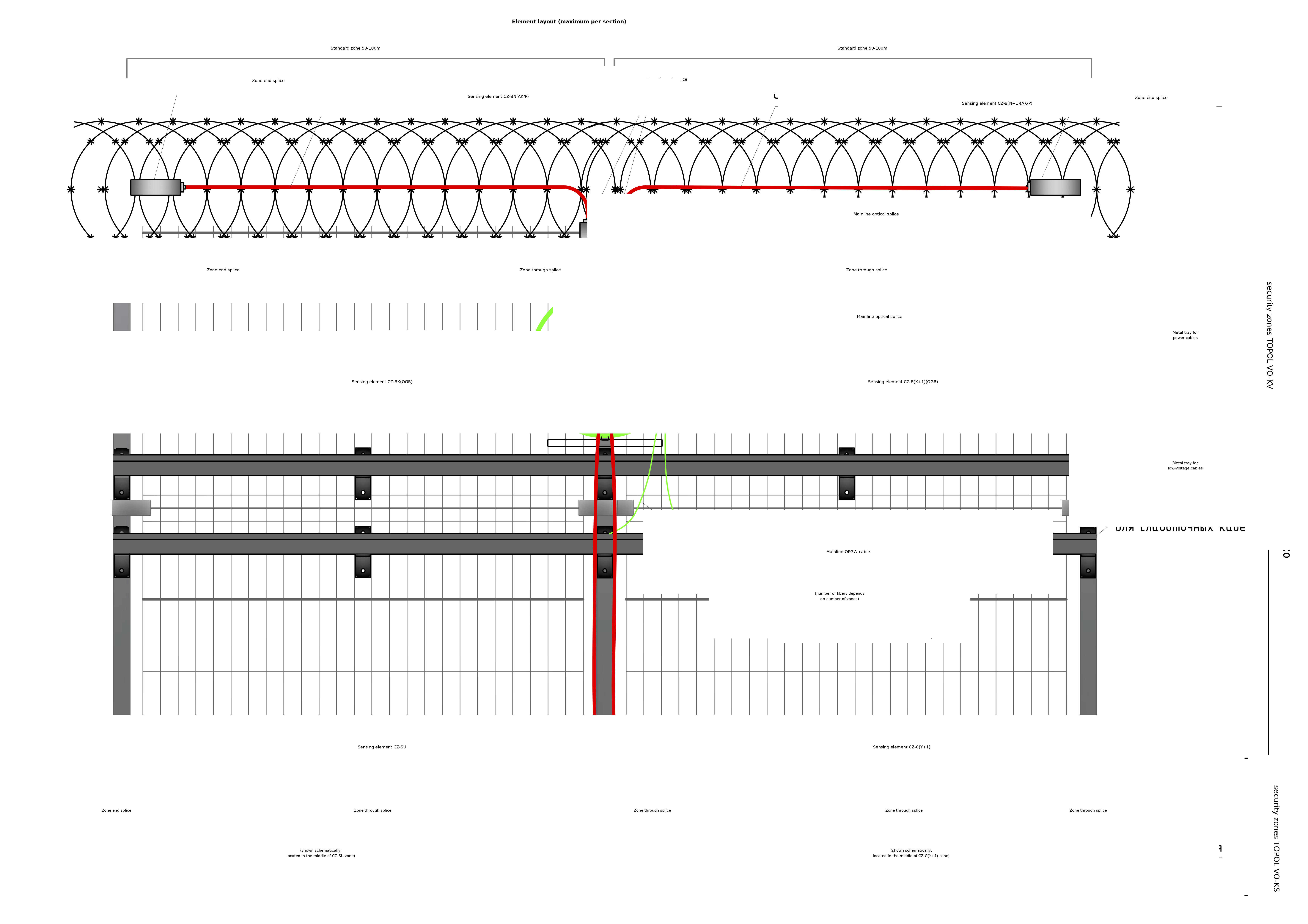
- directly on the fence — welded mesh, profiled sheet, palisade and other light structures;
- on razor tape or a foldable coping arm above a solid fence.

- in the ground beneath a fence of any type — an anti-tunnel security line;
-
in the ground — a seismic security line. Three placement options:
- on the outer side of the fence — detection of an intruder approaching;
- on the inner side — recording the fact of passage beyond the fence. Suitable when there is no clear zone on the outer side (roads, pedestrian areas), and also for verifying the alarms of other security lines;
- along the protected line where there is no fence — a hidden security line.

On special request the cable is manufactured in a metal-free construction variant — for security lines undetectable by an intruder's technical means.
All installation options can be combined in one cable: this is how a multi-layer system with one central unit and one backbone is formed.
Zone connection topology
Regardless of the installation method, zones are connected in one of two ways:
With a separate feeder cable — laid in a tray or buried in the ground. If the backbone is broken, the detector loses contact only with the zone where the break occurred, the rest continue to operate normally.
In a single cable with integrated feeders — more compact and easier to deploy, suitable for rapidly erected and temporary security lines. If the backbone is damaged, contact is lost with the zones beyond the break; the zones before the break keep working.

Each zone of the sensitive cable uses eight-band frequency signal processing: the system works reliably in any climate and across a wide spectrum of natural noise from the environment and the fence. Any band can be excluded from work if the interference source cannot be eliminated — for example, a railway produces background at low and mid frequencies, whereas high frequencies attenuate in the ground before reaching the fence.
For protecting driveways and passages we recommend the active IR barriers of the IVA series.


Sensing Elements
The sensing element (SE) is an optical cable assembled at the factory into zones using splice closures and interferometer mirrors. Two types are available: VO-KV — for fence installation, VO-KS — for burial in the ground.
TOPOL VO-KV — for fences
Installed on welded mesh, corrugated metal, picket fencing, barbed tape. Zone length depends on the version:
| Parameter | VO-KV (1–300) | VO-KV (50–200) |
|---|---|---|
| Zone length (distance between splices) | 1–300 m | 50–200 m |
| Zones per sensing element | 1 | 1 to 6 |
| Maximum lead-in section length | 15 km | 15 km |
| Interferometer arm difference | 60 cm | see data sheet table |
| Minimum cable bend radius | 140 mm | 140 mm |
| Mean time between failures | not less than 60,000 h | not less than 60,000 h |
| Mean service life | not less than 10 years | not less than 10 years |
| Splice closure dimensions | Ø 62; l = 210 mm | Ø 62; l = 210 mm |
| Splice closure mass | not more than 0.5 kg | not more than 0.5 kg |
| Operating temperature | −50…+70 °C | −50…+70 °C |
| Enclosure protection rating | IP65 | IP65 |
VO-KV (1–300) works with TOPOL VO-B-XXX and TOPOL VO/19-B-XXX units, except 19-B-48; VO-KV (50–200) — with the TOPOL VO/19-B-48 unit. The specific zone length is agreed when ordering the SE.
TOPOL VO-KS — for ground
Buried in the ground as an anti-tunneling and seismic security line:
| Parameter | Value |
|---|---|
| Zone length | 1–300 m |
| Zones per sensing element | 1 |
| Maximum lead-in section length | 15 km |
| Interferometer arm difference | 60 cm |
| Minimum cable bend radius | 140 mm |
| Mean time between failures | not less than 60,000 h |
| Mean service life | not less than 10 years |
| Splice closure dimensions | Ø 62; l = 210 mm |
| Splice closure mass | not more than 0.5 kg |
| Operating temperature | −50…+70 °C |
| Enclosure protection rating | IP67 |
The SE is manufactured with a Kevlar or metallic braid protecting it from external mechanical impacts, including rodents, and remains operational at high humidity (98 % at 25 °C). The specific zone length is agreed when ordering the SE.
Documentation
| Device | Passport (PS) | Sensing element |
|---|---|---|
| TOPOL VO/19-B-8 | PS | VO-KV / VO-KS |
| TOPOL VO/19-B-11 | PS | VO-KV / VO-KS |
| TOPOL VO/19-B-22 | PS | VO-KV / VO-KS |
| TOPOL VO/19-B-24 | PS | VO-KV / VO-KS |
| TOPOL VO/19-B-33 | PS | VO-KV / VO-KS |
| TOPOL VO/19-B-48 | PS | VO-KV |
Certificates
| Document | Link |
|---|---|
| TR CU Declaration 004 / TR CU 020 (valid until 24.05.2031) | |
| TC OTB conformity certificate No. MVD.03.001743 |